


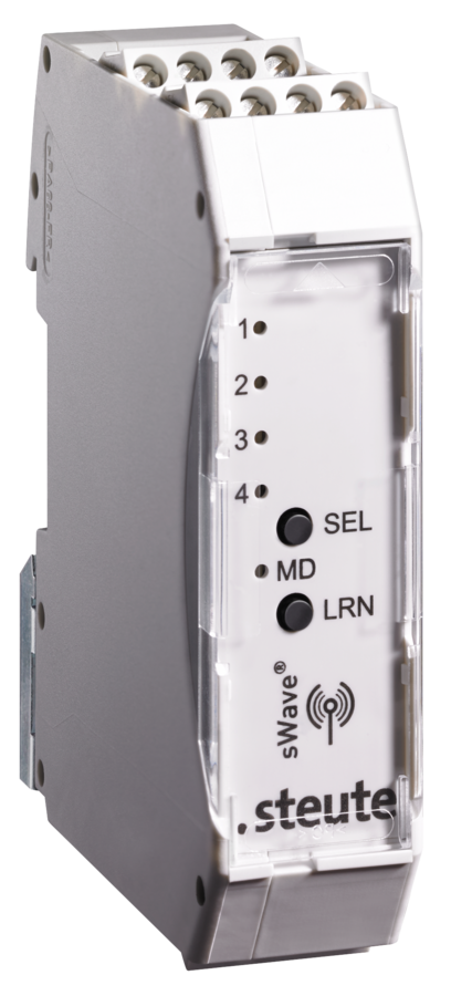

Product features
sWave® wireless technology
4 potential-free relay outputs
4 NO contacts, max. 3 A
Transmitter/receiver assignment by teaching mode
LEDs for indication of switching state
SMA plug-in connector for external antenna
Power-down-function (saves the last signal status from the relay output, if the power supply of the receiver box is interrupted)
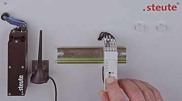
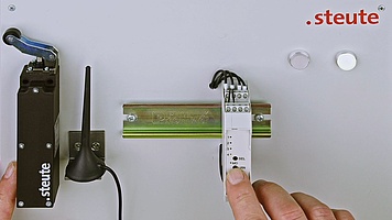
Notes
External antenna always required for optimum wireless range.
Technical data
General technical data
Applied standards
EN 60947-5-1, EN IEC 61000-6-2, EN IEC 61000-6-3, EN 61000-4-4, EN 61000-4-5, EN 61000-4-6, EN 60068-2-6, EN 60068-2-27, EN 301 489-3, EN 300 220-2
Enclosure
polyamide, self-extinguishing UL 94 V-0, RAL 7035
Degree of protection
IP20 (IEC/EN 60529)
Number of channels
4
Mounting
DIN rail mounting
Connection
screw connection terminals 0.14 mm² - 2,5 mm², stripping length 8 mm
Teachable transmitters
40
Outputs
4 NO contacts (relay)
Rated operating current/voltage Ie/Ue
max. 0.1 A/24 VDC -15 % … +10 %;
output contacts: 3 A/250 VAC; 3 A/24 VDC
Utilisation category
AC-15; DC-13
Rated insulation voltage Ui
250 VAC
Rated impulse withstand voltage Uimp
2.5 kV
Display
green LED: ready for operation,
orange LED: signalling of switching state
Telegram rate
max. 1440 telegrams with repetitions/h
Degree of pollution
2
Ambient temperature
–20 °C … +55 °C
Storage and shipping temperature
–25 °C … +85 °C
Note
Inductive loads (contactors, relays etc.) are to be suppressed by suitable circuitry.
Switching contacts are not suitable for capacitive loads.
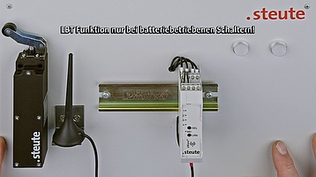
Allows configuration of LBT and status signal of the transmitters
Wireless approvals
Japan: ? ARIB STD-T108: 204-610002
Weight
88 g
Wireless technology
Frequency
916.5 MHz (Japan)
Data rate
66 kbps
Channel bandwidth
520 kHz
Protocol
sWave®
Transmission power
< 1 mW
Dimensional drawing

Further drawings

A = Optimum mounting
B = Possible mounting
C = Unsuitable mounting
Downloads
Other interesting products


Alternative wireless receiver with 4 potential-free relay outputs (4 change-over contacts)


